
Intel's Real Mode
The funny thing about having CPU registers narrower than your architecture's address bus is that you can't store some of the larger memory addresses in a single register. Although still somewhat of an issue on certain embedded platforms and microcontrollers, this issue gained a large amount of exposure in the context of the 16-bit Intel CPUs—namely, the 8086 and the 8088. These chips were equipped with a 20-bit external address bus, yet the internal registers were only 16-bits wide. So, this may leave you asking yourself:
"How did those brilliant Intel engineers make it possible to address \(2^{20} = 1,048,576 = 1\) MB of memory using 16-bit registers capable of only counting up to \(2^{16} = 65,535\)?"
Well that, my friend, is the story of Real Mode.
The Big Idea
The story of Real Mode is one that is continued to be told to this day. Thanks to Intel's policy of maintaining backward compatibility between processor generations, modern Intel CPUs (such as the Core i7) initially boot up into the so-called "Real Mode" originally used by the ancient 8086/8088 CPUs. So, what is Real Mode? Simply put, it is a memory segmentation scheme.
Intel solved the problem of addressing 1 MB of memory using 16-bit registers by employing memory segmentation hardware that converts logical addresses into linear addresses. In short, programmers would write their programs using logical addresses and the segmentation hardware would convert these logical addresses into 20-bit linear addresses, which would then be placed onto the 20-bit wide external address bus. This all sounds great, but what is a logical address and how does it magically get converted into a 20-bit linear address?
Paragraphs
Real Mode is based around the idea of dividing physical memory into 16 byte paragraphs. Simply put, starting from physical memory address zero, we call every 16th byte the beginning of a new paragraph. The situation looks like this:
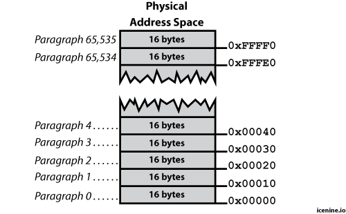
Simple, right? Now that you understand paragraph boundaries, we can talk about logical addresses.
Logical Addresses
In Real Mode, memory is accessed by the programmer using logical addresses.
A logical address has two parts: a segment specifier and an offset
specifier—consequently, logical addresses are written with a colon
separating the two (e.g. segment:offset). The segment specifier, well,
specifies one of the 65,536 physical memory paragraphs as the beginning
of a 64 KB segment. Once a segment is specified, it generally doesn't
change very often. The offset specifier, however, changes all the time
since it is used to access individual bytes of memory within the 64 KB
segment. So, the overall idea is to specify a 64 KB chunk of physical
memory called a segment, which starts on a 16 byte boundary called a
paragraph. We then "play around" inside this so-called segment by
specifying different 16-bit offsets.
Logical Address Translation
Taking a logical address of the form segment:offset and translating it
into its corresponding physical memory address is an extremely
straightforward process. Consequently, the physical hardware is also
relatively simple. All that is really needed is a 20-bit shift register
and an adder:
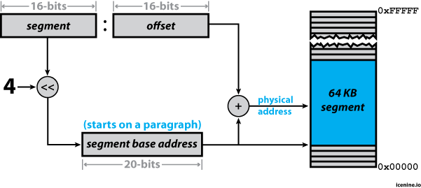
As shown in the figure, the segment and offset registers are each 16-bits wide. The value loaded into the segment register is effectively the paragraph number we want the 64 KB segment to start at in physical memory. This paragraph number is converted into the physical address of the paragraph by simply shifting it 4 bits to the left—thereby forming a 20-bit physical base address for the segment.
It is then possible to address any of the 65,535 bytes falling after the base address by simply adding the 16-bit offset to the 20-bit physical base address of the segment.
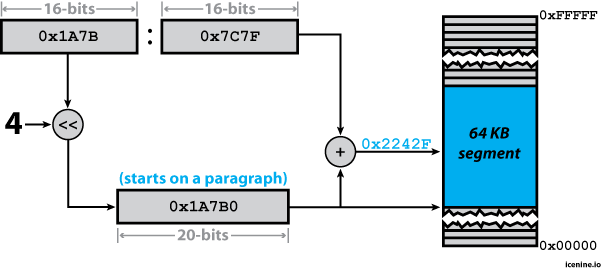
To make this a bit more clear, let's graphically look at how the
segmentation unit would translate the logical address 1A7B:7C7F into
the 20-bit physical address 2242F.
Segments in Action
All programs consist of a code (a.k.a. text) segment, a data segment, and a stack segment. Now-a-days these so-called "segments" do not actually translate into the 64 KB segments we are talking about here. However, once upon a time they did (and when running in Real Mode, they still do). Consequently, the Intel CPUs have special segment registers for each of these segments that form the base anatomy of a program:
-
Code Segment (register
cs) — This memory segment contains the instructions comprising the program, which are executed by the CPU. -
Data Segment (register
ds) — Contains the program's global variables. -
Stack Segment (register
ss) — The program's stack. Variables local to a function are stored here as well as function parameters and return addresses. -
Extra Segment (register
es) — This is literally just an extra segment that the programmer can use at his or her convenience. Consequently, its use is completely optional.
Since segments are allowed to overlap, there are multiple configurations programmers can choose from when designing the memory layout of their program. These different configurations are more commonly referred to as memory models—and they each have names.
The Tiny Model
This model is pretty simple. Simply put, all segments overlap. The code segment, data segment, stack segment, and the extra segment (if it is being used) all start on the same paragraph. This means that the entire program (instructions, data, stack, everything) must fit into 64 KB of memory. If you use this model, your program is indeed tiny. This is a choice option for simple command line utilities.
The Small Model
This model is similar to the Tiny Model, in that the stack and data segments still start on the same paragraph—overlapping each other completely within a shared 64 KB block of physical memory. The code segment, however, starts on a different paragraph—potentially having up to 64 KB of physical memory all to itself.
The Compact Model
Starting with this model, things start to get a little more creative. Here, the compact model provides still provides a single code segment, but utilizes multiple data segments.
The Medium Model
This model supports multiple code segments, allowing for more complex programs, however only a single data segment is designated.
The Large Model
The model is exactly what it sounds like. Large. Well, for the time it was considered large... Programs written using this model have multiple code segments as well as multiple data segments.
In Closing
In this article we talked about the fundamental ideas necessary to understand the translation of logical addresses into linear addresses. We introduced the idea of a paragraph and discussed how logical addresses designate a paragraph as the beginning of a segment. We covered the idea of using an offset to locate individually addressable bytes within a segment, and we took a look at how 16-bit segments and offsets are formed into 20-bit linear addresses by using a shift register and an adder. Finally, we looked at the specific segment registers offered by the Intel architecture and touched on a few different memory models employed by programmers operating in real mode.